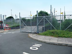
Here at SEA UK we work with some of the most talented installation companies in the country. Today we are on site with Richard the owner of Garage Door Restore West Midlands (GDR) and his team. They have recently completed a traffic management system for a Casino in Birmingham. GDR’s customer required an entrance and exit barrier that could cope with the 24 hour demands of the Casino, located near to Birmingham City centre.
The Entrance
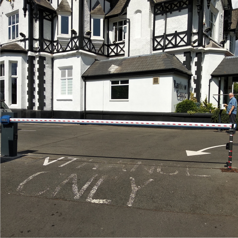
It was decided that a vehicle detector would activate the traffic barrier, allowing free entrance to the site. Richard, in consultation with our specification team and the Casino, chose a Storm traffic barrier system. The Storm is the perfect traffic barrier for this site with up to a 7.5m beam and 24V high intensity usage motor, capable of near continuous operation.
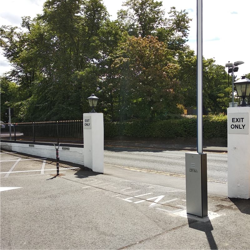
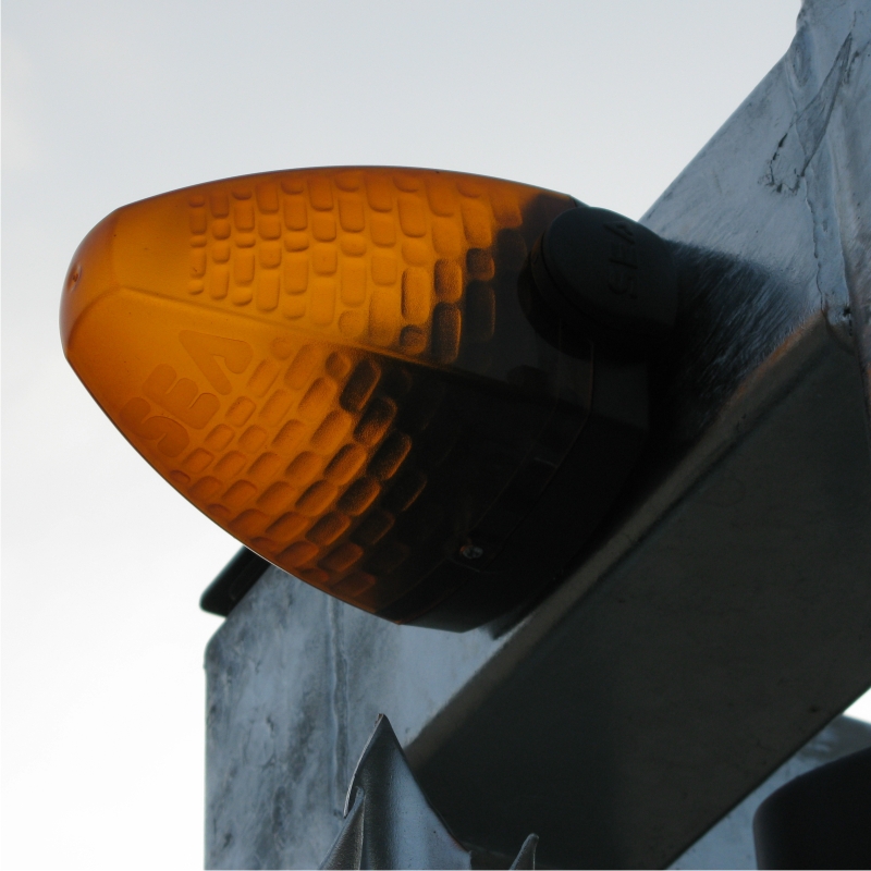
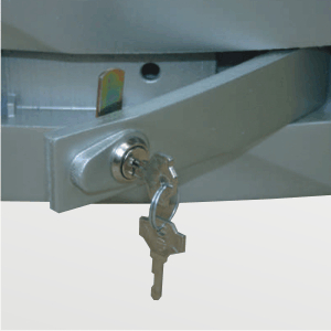
Richard has set the traffic barrier back from the road to make room for the loop detector and added new railings with brick pillars to further control traffic flow. The 24V motor on the Storm provides in built current sensing safety and low heat build up when in continuous use. In this case the 7.5m beam was not needed and a 6m beam was used instead. Finally a pair of Photo 60 anti vandal photocells were added for additional pedestrian safety. Security was increased by fitting a magnetic lock at the end of the barrier, securing the beam against the fork support when in the closed position.
The Exit
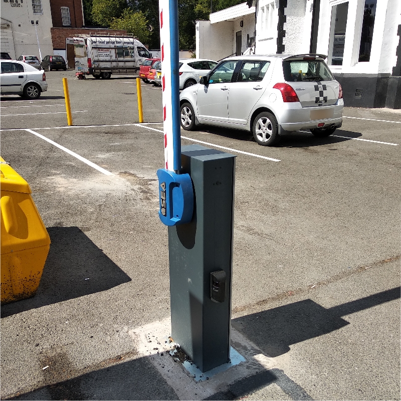
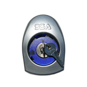
For the exit traffic barrier a Sprint system was installed instead of the Storm, as the barrier length required did not exceed 5m. The Sprint Electro-hydraulic system allows for continuous operation with built in current sensing and limit switches for automatic learning. Anti vandal photocells and a magnetic lock were chosen again for added vehicle/pedestrian safety and security. A token reader has been sited near the exit barrier preventing unauthorised vehicles from using the car park and leaving unhindered. Car park users now need to obtain a token from inside the Casino to leave the premises.
Richard from GDR West Midlands says, “Our customer needed an automatic gate system to prevent unauthorised use of their car park and the SEA traffic barriers are the ideal solution.” He goes on to say, “The support SEA have provided has helped keep our costs down and get this job finished on time and on budget.”
For more information about this automatic gate system or one like it, contact our technical sales and specification team on 0121 433 3348. To be put in touch with a local SEA installer like Richard fill in our contact form here.
Here are some basic trouble shooting tips to help speed up any electric gate repair. However, before we start, please remember that electric gate system can be dangerous to you and dangerous to other gate users.
Any changes to the electrical system should be carried out by a qualified electrician or gate engineer. If you make any changes or adjustments always consider the dangers that you may create.
If you ever feel out of your depth, stop, contact us or find an installer. With that warning out the way let’s get started!
1. Look at the warning lights
Many systems will have a warning, or a flashing light fitted to visually indicate what the gate systems is doing. Warning lights can be set up in several different ways, often giving a slow steady flash when the gates are operating normally. If you see your light flashing followed by a long break, count how many flashes there are between each pause. This number will correspond to a troubleshooting table on some Control Panel PCB’s, such as the Gate 1 and Gate 2. Once you know where the problem lies take a closer look at the affected part of the system.
2. Check for power failure.
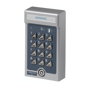
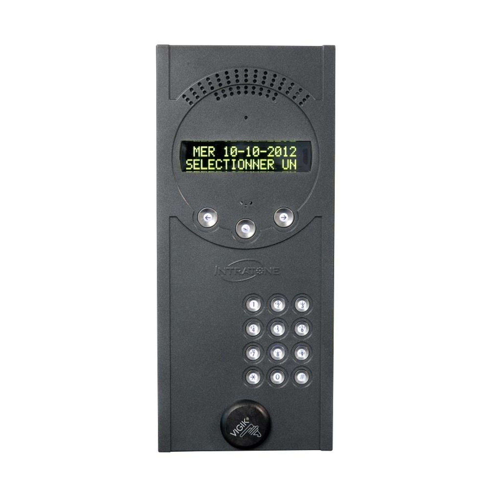
A common problem is simply that the mains supply feeding the gate has tripped. Check all the attached devices like intercoms and code pads for any lights that will indicate they still have power. On accessories like photocells you can wave your hand in front of the photocell beam and listen for a click. If there is no response a power supply problem is possible, check your fuse board to see if the power can be turned back on.
3. Is the Gate stuck open or closed?
If the gate is stuck open it means the gate was closed, responded to a start signal and drove open before having a problem. This situation often indicates a problem with the safety equipment, typically the photocells which allow opening when they are broken but prevent closing. With sliding gates this could indicate a failure of the limit switch.
When a gate is stuck halfway it will be down to one of 3 things. A power cut as mentioned in tip 2, a point of high physical resistance as in tip 4 or an interruption from a safety edge or rotation sensor reacting to an impact. If a safety edge is activated they can sometimes become jammed. Clicking or squeezing the edges can often cure a failed system.
On the other hand, if the gate is stuck in the close position it means it is not receiving a start signal or cannot drive open. This is a little harder to solve. Normally, it will be either a problem with the start device not linking to the main PCB, a safety device preventing operation or an issue with the gate operator. For example, the gate being forced, which brings us to tip 4.
4. Check for signs of damage.
Check for any signs of damage on the gate or motor. Often problems with an operator not moving can be traced back to an accidental hit by a vehicle or an act of vandalism. Damaged brackets, motor cables, and scuffed paint work all point to the gate being forced. Sometimes the signs are subtler so when in doubt try tip 5.
5. Manually open and close the gate.
If the gates look ok and you can hear the motor trying to run but nothing happens wait until the system stops and then put the motors on to manual and slowly push each gate leaf open and closed using the minimum force possible. On you can try to move sliding gates with just a finger, but swing gates will need a little more force. If the gates run free the problem could be electrical but if you encounter one or more points of resistance do some more investigation in these areas.
For example, on sliding gates it is not uncommon for the wheels which support a sliding gate to wear out over time. Often the gate motors are powerful enough to keep going. However, if the wheels wear enough the gate will drop and begin to bind on the toothed drive rack the gate motor pushes against. Meanwhile on swing gates a similar situation caused by wear in the hinges can lead to the gate dropping, sometimes even to the point where it will drag on the floor. If you are finding it hard to put your system into manual mode, his can show that the gate is mechanically jamming. Binding issues like this can cause a gate to work perfectly well in certain positions and not at all in others.
6. Check the start inputs.
If you are clicking away with a key fob, nothing is happening, and the gates will not open, try using the code pad, a neighbour’s key fob or an intercom to give a start signal to the gate in a different way. This will tell you if there is a problem just with your key fob, with all key fobs or with all start devices.
Finally, an often over looked source of annoyance for many gate installers is the unknown hold open switch, timer, intercom latch or ground loop. Check with the home owner to see if they have any way of holding the gates open for deliveries, or if the gates open automatically at certain times of day. After all there is nothing more infuriating than finishing your work on site only to see the gate open and stay open for seemingly no reason at all. When the home or business owner isn’t available double check the system for time clocks and hold open switches. If none are found and you are Electrically competent, you can open the main control panel check the control panel and check for signs of a permanent start (as per the control panel instructions).
Open the control panel and look at the digital display or LED’s if a safety device has failed or a start signal is permanently applied this can be ascertained here. We can then advise you where to look next.
In the end
Gate systems are sophisticated, often complicated pieces of technology. They are exposed to driving rain, flooding, freezing temperatures and scorching heatwaves, year after year. Needless to say, this is by no means an exhaustive list of troubleshooting strategies. We would urge end users to seek the help of a qualified electric gate installer sooner rather than later. We would also urge gate installers not to feel embarrassed about contacting a technical help line as there are hundreds of minor issues which could potentially cost you days on site and our technical team is ready to help!
One question our technical team gets asked constantly is “What kind of gate operator do I have?” Today we are going to answer that question once and for all.
Before we start to describe the labels we recommend always following these steps when arriving on site:
Take a picture of the label.
Measure the operator length if its an above ground swing gate system.
Call us from site (if you are at all unsure).
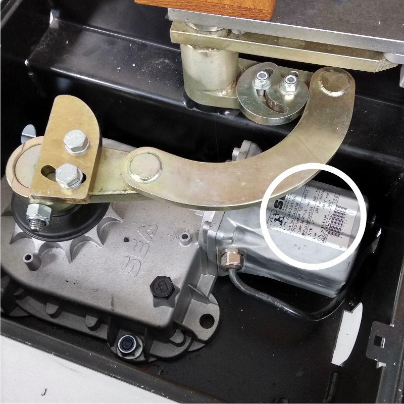
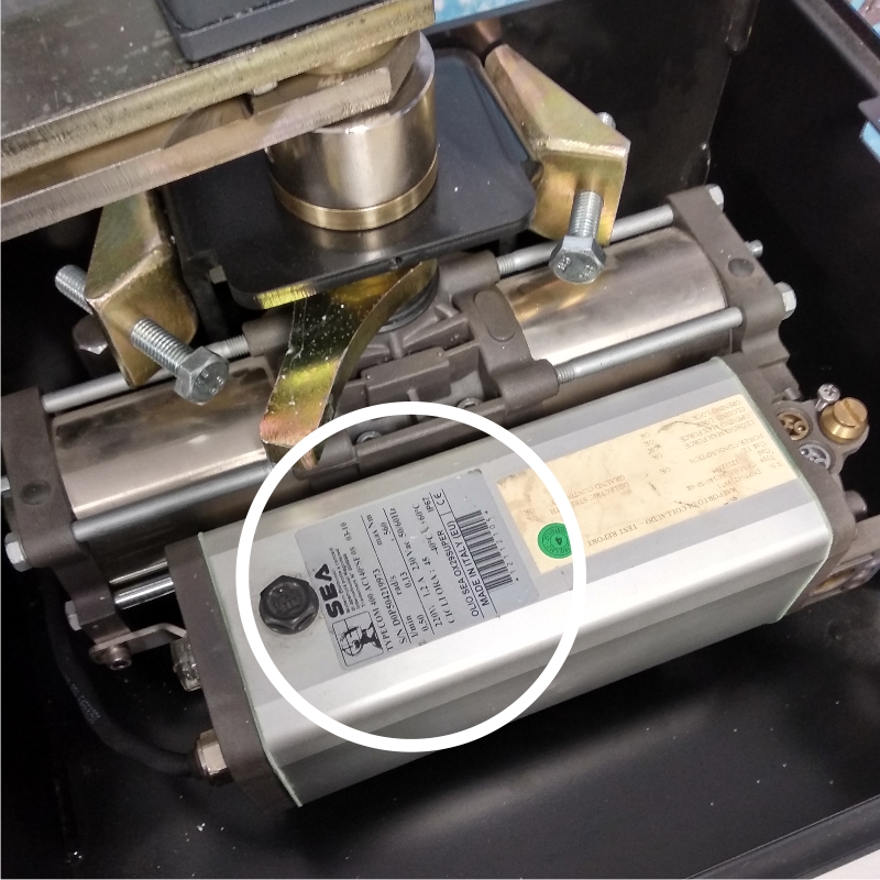
These first thing many people wonder is where are the operator labels? Where do you look to find them? Well when you know what you are looking for they become very easy to find. The operator label will be silver, with black writing and will be placed on the top or side of an operator. Look at these examples below where we have highlighted the operators label.
Label on a Field system
Compact Label
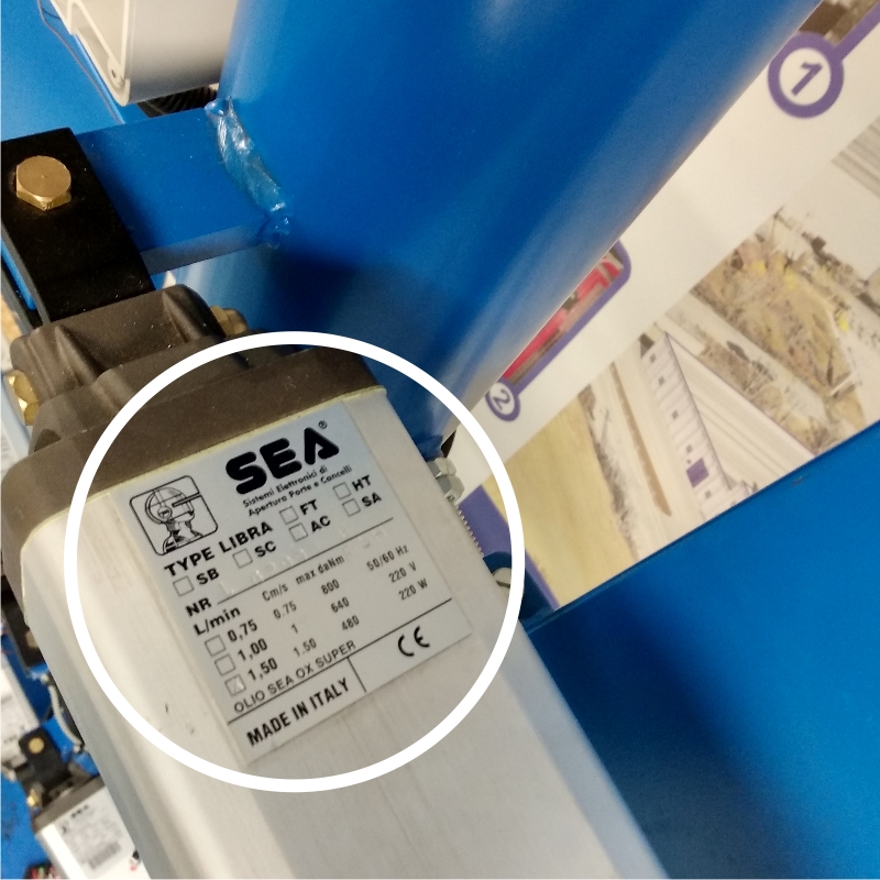
Old Libra Full Tank Label
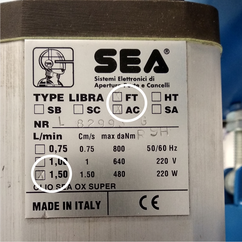
For the next step you need to look at the label and try to find the bar-code. This will be visible on all modern systems. Just beneath the bar-code you will see an 8 digit number and this is the product code needed to identify the model. Old operators will not have a bar-code. In that case look for an ‘X’ mark in the squares to find the motor information. For example in the Old label below there is an X on the FT, AC and 1.5 l/min box, signifying that this is a Full Tank AC 1.5 litre/minute operator.
Look for numbers under bar-code on newer labels
On old labels look for the ‘x’ to find information.
Sometimes for the old operators we will need additional information such as the piston stroke of the operator. This is because SEA’s oldest systems can date back 30 years and at the time an operator might have been made in only one size.
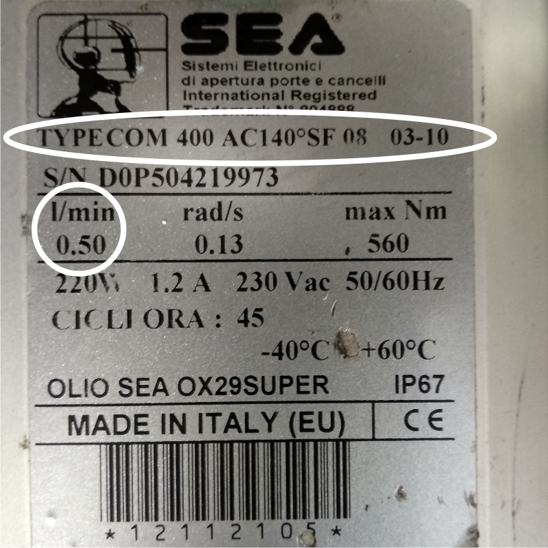
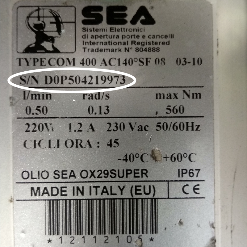
On new operators If the label is scuffed or damaged information about the operator can still be found else wear on the label. In the example below the operator information is found on the top line next to the word TYPE and on the second line under L/min. The final piece of information is the serial number and can be found next to S/N; the serial number provides a date of manufacture for a gate motor and also shows who assembled the operator in the factory and who tested the operator.
Other useful information on a Compact label.
Where to find a Serial Number on a lablel.
Remember if you are ever unsure take pictures of the label, measure length of the operator, and contact our technical team from site. We are always on standby to help out, you can reach us Monday to Friday 9am to 5pm on 0121 433 3348.
HOW TO FIT ELECTRIC GATES: Rear Bracket Geometry for Swing Gate Motors.
Hello and welcome to a new series of articles published by SEA UK showing you how to fit an electric gate system. In today’s article we are going to discuss how to set up the rear bracket geometry for an above ground electric gate Ram. Our method is simple and easy to follow and can be applied to any manufactures product, so you can get it right every time.
Gate rams are one of the most effective gate systems when fitted correctly, but if you get the rear bracket position wrong you will have a system which either works badly with no power, is dangerous or can be easily damaged.
First steps
There are 3 important elements which we must discuss before we go into detail about how to fit an above ground swing gate system:
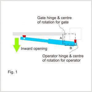
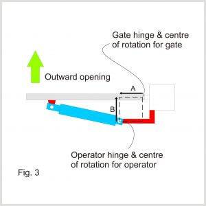
Gate/Motor Centre of rotation is the point which the gate or motor rotates around. This will always be in the centre of the gate hinge or at the back of the motor where it is pined or bolted to the rear bracket (see Figure 1 to 3 below).
Stroke length is how much a gate motor can change its total length by, we will talk more about the importance of this later on.
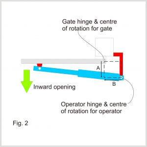
A and B measurements play a crucial role in correct installation. They can be quite hard to explain but the 3 diagrams below will show how to find the A and B measurements. Figure 1 and 2 show examples of standard inward opening gates but Figure 3 shows an example of an outward opening gate, notice how similar it is to Figure 2.
A Basic Installation Example
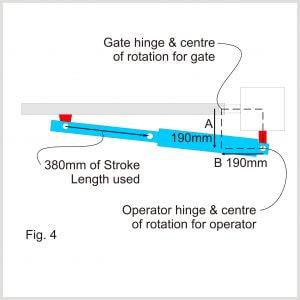
To successfully fit any piston or ram type automatic gate system you must first know the operators Stroke length. The Stroke determines the A and B measurements which can be used. In order to achieve the most control over each gate leaf you must take the stroke length in millimetres, subtract 20mm and the resulting measurement can then be divided by 2. These become your A and B measurements. Let’s use a the SURF 250 gate operator, which has a Stroke length of 400mm as our example. 400mm – 20mm = 380mm, 380mm/2= A: 190mm & B: 190mm.
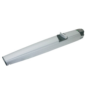
Surf 250 Motor
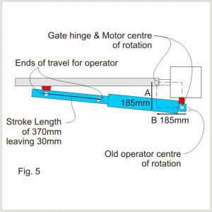
A longer Stroke Length allows for more adjustment when fitting. With the Surfs long Stroke Length you could subtract 15mm from each end of travel giving operator a total piston stroke of 370mm; when split between A and B, this gives 185mm to each. Now there is extra margin to fit the operator comfortably and still have strong leaf locking, as in the figure 8 example below.
When A and B are not balanced?
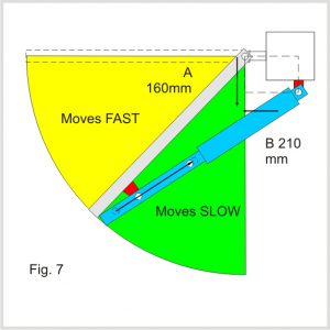
A lot of problems can arise when the A and B measurements are too different. First let’s look at what happens when there is a relatively small imbalance. Returning to our previous example, what would happen if A is larger than B? In Figure 6 the A measurement is 210mm and the B measurement is 160mm. An imbalance will cause the operator to speed the gate up as it approached the open position and as the gate returned towards the close position it would lose momentum, reaching the close point with very low power (this can cause problems with electric locks).
If the reverse is true and B is large than A the gate operator will be moving faster as it comes to the close position, carrying more momentum but will be slow when opening and sometimes may not fully open. This can lead to unsafe gates, see the example in Figure 7 above. There will be situations where these imbalances cannot be avoided, but if installers are aware of the way a gate will change, measures can be taken to minimise the negative effects.
Extreme problems caused by poor geometry.
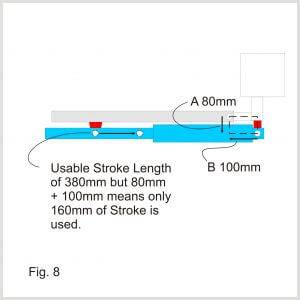
When the difference between the A and B measurements is too high, or when very little of the operator’s stroke length is used you will find that the operator will move very fast but with very low force, or the operator will not move at all. As well as this, operators will be vulnerable to excess forces and could be easily damaged by a person or even the wind.
In figure 8 below a very small A measurement and a small B measurement has resulted in the gate operators having low power and low resistance to excess forces. This is because the combined A and B measurements only uses a tiny fraction of the operator’s total Stroke Length.
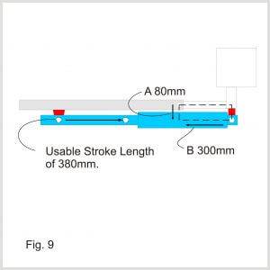
However, if the A measurement is still small but the B measurement is extended to use the full piston stroke there will still be a significant problem. In Figure 9 above, the A measurement is still 80mm, but B has been extended to use the remaining 300mm of the 380mm available. Unfortunately, because the front and rear bracket rotation centres are in line, causing the operator to be parallel to the gate, the operator cannot pull back. In this configuration the operator will also be extremely poor at resisting excess forces. Remember for a Ram type operator to move a gate there must be a triangle and in figure 9 the triangle is non existent.
Finally, if the A measurement is large but the B measurement is small, the Motor will hit the gate as it opens. This problem is usually spotted early on site and so very few people report this, but we think it is still worth mentioning here.
In conclusion for perfect geometry and a flawless ram operator installation simply find the operators stroke length, subtracted 10-15mm from each side and divide by 2. The resulting number will be you’re A and B measurement which you can use to find the correct location for the motor centre of rotation relative to the gate centre of rotation.
If you have any questions feel free to contact our technical team, or leave a comment below.
Several weeks ago, we wrote an article on the new SEA Position Gate device, demonstrating how an SEA Half Tank or Mini Tank system could pass force tests with ease. But what is a Force Test? Put simply when a powered gate meets an obstruction, be it a person, animal or vehicle, the gate applies a force to that person. A small force from a safe gate would result in, at worst, a bruise. However, a large force applied by an unsafe electric gate could result in serious injury or severe property damage.
The gate Force Tester was created to help electric gate installers test the safety systems on their gates. The test results show that the installed gates comply with EN12453, EN12445 and EN13859 safety legislation. Proof of compliance is required for any gate operated by a business or in a public place.
Force Testers measure the initial impact force and how the force changes over time. The results combine to show a graph like the example on the left (used in our previous blog). Force is shown on the vertical X axis and time on the horizontal Y axis. Notice that a larger force, shown by the pink area, is acceptable for a short time on initial impact, providing it drops away over time through the yellow area before disappearing completely.
Passing a force test can be achieved in different ways and each gate system is unique. Some can use current sensing systems such as our Field or Surf. Others will make use of encoders, like our Half Tank or Lepus. For the rest, safety edges and light curtains can still be used to make any gate system safe. In each case the same force test will prove if the chosen safety system is performing its roll correctly.
Force Testers as pictured above have revolutionised gate safety and every day thousands of force tests are carried out across the county. As a member of the DHF (Door and Hardware Federation) SEA UK is at the fore front of gate safety legislation. We regularly provide training for full compliance, which covers: the proper use of force testers, how to use force test data to produce hand over documents and how-to CE mark gates.
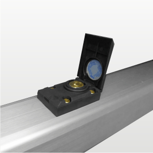
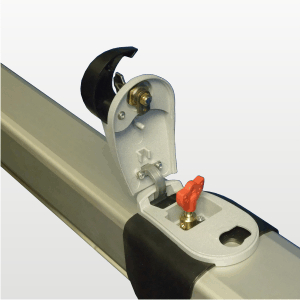
SEA are constantly striving to bring new safe gate systems to the market; to that end the company has made the Position-Gate. This device will enable Mini Tank and Half Tank systems to accurately “feel” where the piston rod is, while the gate is travelling open or closed.
By sensing the exact position of the piston rod, the Position-Gate knows where the gate leaf is in it’s travel, how fast it is moving and precisely when it will encounter a physical stop. Therefore, the Position-Gate can be used as an auto learn device and a stop and reverse safety device. It can also operate below the 50mm threshold, where traditional current sensing devices and encoder systems do not work effectively.
SEA UK Position-Gate Force Test Results.
At SEA UK we periodically tests our product range to ensure the highest standards of reliability are maintained. While testing the Position-Gate we carried out a series of Force Tests to confirm the Position Gate worked as intended.
The Gate.
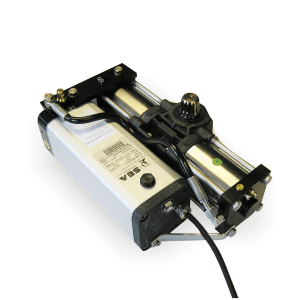
These tests were performed using our repaired motor test gate; if you sign up to one of our free training courses, you will be working with this gate. Our test gate is 2.5m long, weighing approximately 280kgs when fully loaded. To better simulate site conditions, the gate has standard eyelet hinges, with weight added to the front of the gate leaf to increase momentum and loading on the motor. The motor is connected to a central beam which is unsupported by vertical bars. This is an intentional design to simulate common flexing found in many site situations. The operator used is a Half Tank 100, 270mm piston stroke, 230V AC motor. The control system is a Gate 2 DG, 230V control panel.
SEA Test Gate 2.5m long & 280kgs in weight.
SEA Test Gate With Half Tank 100 motor
Testing 2.5m Gate Leaf, Weighing 280kg.
When force testing a gate system, measurements must be taken at the bottom, middle and top of the gate leaf; as well as at different distances away from the close stop position. The diagram below shows where these tests are made and provides a useful numbering system to match up with the results later.
Test Position 8
The first test is typically carried out in position 8, the gates centre, at 500mm from the close stop position. At this point the gate leaf has entered slowdown and is moving at roughly half speed; our gate has no safety edges or other forms of cushioning to absorb the impact.
Point of Measure
Description of tests
Fd [N] -Measure – Limit
Td [s] – Measure – Limit
Fs [N] – Measure – Limit
Fe [N] – Measure – Limit
Result
8
Height: at the center of door, or 2500mm above the floor, when the height of door is >5000 mm. Gap: 500mm from main closing edge and the opposing edge.
119/400
0.00/0.75
24/150
0/25
PASS
The results above show a PASS has been achieved, but more information can be seen from the force graph produced by Microtronics Blue Force software. The initial impact is detected very quickly and the gate starts to reverse. The excess weight added to the gate leaf and the lack of central vertical supports on our test gate creates a wobble, this can be seen by the waves in the graph. As the gate moves away from the tester the waves diminish, before falling to 0 as the gate fully clears the tester. The gate is moving away from the obstructions within approximately 2.0 seconds.
This PASS is possible because the Position-Gate knows the precise position of the piston rod. The control panel knows that the gate is within the gate slowdown phase (the 500mm danger area) and is expecting lower momentum with pushing forces adjusted below the 150N threshold. It can therefore accept a longer reverse time allowing for wind slowdown at lower forces.
Test Position 10
Test are not often performed at 1m distance because the motors are moving at full speed. Many systems especially current sensing versions, struggle to pass at this distance due to site conditions and motor reaction times.
Before carrying out the force test SEA engineers perform a separate test to simulate site conditions and the effects of wind on the gate. With default pressures used on the Half Tank our engineers added a 90N (9kg) resistance to the gate. As expected the motor continued to open and close with this added resistance.
Next, with the same pressures, the resistance removed and the gate travelling at full speed again, our engineers carry out the Force Test. A clear PASS is recorded and it would even be possible to increase motor pressures for the Half Tank operator to cope with increased wind loadings if necessary.
Point of Measure
Description of tests
Fd [N] – Measure – Limit
Td [s] – Measure – Limit
Fs [N] – Measure – Limit
Fe [N] – Measure – Limit
Result
10
Height: at the center of door, or at 1000 mm above the floor. Gap: 1000 mm from main closing edge and the opposing edge.
372/1400
0.59/0.75
12/150
6/25
PASS
As we can see form the table above and graph below the Position-Gate allows the system to pass the test. Once again, a small bounce is recorded due to the style and construction of the gate, as well as the added weight at the end of the gate leaf.
Test Position 1
More tests are carried out at positions 1 and 2. Here again there is a small wobble due to the excess weight, our testers have added to the gate but importantly the Position-Gate has slowed the motor down ready for the gate to meet the physical stop. This means the initial impact is just above the 25N Fe mark.
Point of Measure
Description of tests
Fd [N] – Measure – Limit
Td [s] – Measure – Limit
Fs [N] – Measure – Limit
Fe [N] – Measure – Limit
Result
1
Height: at 50 mm from bottom edge of the door. Gap: 50mm from main closing edge and the opposing edge.
51/400
0.00/0.75
18/150
0/25
PASS
Many encoder and current sensing systems must switch off at distances around 50mm or risk recording a false positive, but the Position-Gate continues to operate up to the physical stop position. This can render other systems ineffective at protecting the small closing gaps at the end of a gates travel. The Position-Gate measures the position of the motor ram switch off distance, which can be accurately and electronically adjusted; resulting in a passed force test.
Our engineers report that when the motors are set up to use low pressure, the impact force of the closing gate is below 25N (not registering on the Force Tester). This would not be recommended on site as it would cause reliability issues. It does however, underline the fine control which can be achieved with the Position-Gate system and reliable hydraulic operators.
Position-Gate Qualities
When considering gate safety products, it is important to understand the relative qualities of each product. The Position-Gate may not be the perfect solution for every site. For example, a very long gate leaf reduces the effectiveness of the system. A close boarded gate can act like a sail; the motor pressures may need to be increased to provide reliability, resulting in the FS Max being above 150N. Furthermore, certain areas of a gate such as the hinge area and curb crushes could still be dangerous and need protecting.
Summary
The Position-Gate is a powerful new tool for SEA hydraulic electric gate systems and will lead to improved safety on many sites. It can pass force tests at all locations allowing the adjustment of the motor power to suit site conditions. However, it should be used in conjunction with a proper risk assessment and other safety devices such as Safety Edges, Photocells, and Hinge Guards.
Comply with gate safety laws & use SEA’s handover document: SEA Handover Doc
SEA has been championing the highest gate safety practices since our company formed. We were one of the first companies to offer a dedicated safety edge contact for our control systems and have been recommending safety edges be fitted as standard for over a decade.
Today SEA are active members of the Gate Safety community and hold certifications in gate safety with the DHF (Door and Hardware Federation) as well as Gate Safe. We hold regular personalised training sessions helping gate installation companies across the country understand the regulations and find practical solutions to common safety concerns associated with electric gates.
At the request of our customers we have created a Handover document containing guidance on gate risk assessment, how to CE mark a gate system as well as important information for end users. While it is impossible to conceive of every eventuality, the SEA handover booklet provides a clear starting point for the installer.
Bespoke PDF versions of the handover document are available on request to account customers. When asked about why SEA had taken the step to produce the document Managing Director Joffre Reynolds said, “We always strive to give our engineers and customers the best service and equipment possible. The handover document will assist the smaller companies to enable them to fit safe and compliant gate systems more confidently.”
This website uses cookies to improve your experience. We'll assume you're ok with this, but you can opt-out if you wish.AcceptRead More
Privacy & Cookies Policy
Privacy Overview
This website uses cookies to improve your experience while you navigate through the website. Out of these, the cookies that are categorized as necessary are stored on your browser as they are essential for the working of basic functionalities of the website. We also use third-party cookies that help us analyze and understand how you use this website. These cookies will be stored in your browser only with your consent. You also have the option to opt-out of these cookies. But opting out of some of these cookies may affect your browsing experience.
Necessary cookies are absolutely essential for the website to function properly. This category only includes cookies that ensures basic functionalities and security features of the website. These cookies do not store any personal information.
Any cookies that may not be particularly necessary for the website to function and is used specifically to collect user personal data via analytics, ads, other embedded contents are termed as non-necessary cookies. It is mandatory to procure user consent prior to running these cookies on your website.